The purpose of the physical layer is to send a stream of bits from one node to another. It doesn’t matter what the bits represent. Email, Web pages, digitized telephone bits are all the same. We will only consider the transmission of binary digital data at this time.
Data is usually sent over a single channel one bit at a time. A single wire transmits the bits one after another. Some systems for local communications send multiple bits at a time. Data transmitted between a PC and a printer is sent 8 bits at a time over a printer cable. Most networks, particularly long distance connections, send data one bit at a time. Over long distances there can be a problem with all of the bits arriving at the final destination at the same time.
Data can be sent synchronously or asynchronously. Bits can be synchronized so that each bit is sent at a specified time after the previous bit. Bytes can be sent synchronously so that one byte follows another.
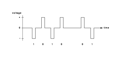
Binary data can be sent over a wire by varying the voltage on the line. Positive voltage can represent a 1 bit and negative a 0. In the below diagram, a 0 or 1 bit can be sent at any time. This is bit-wise asynchronous. (Note that very few existing systems use this method.)

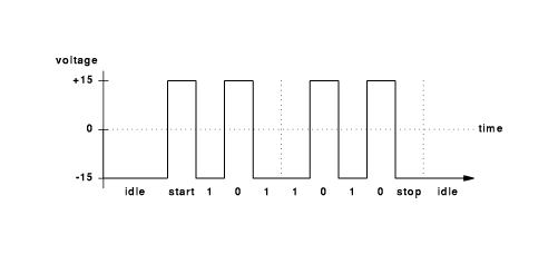
While bit-wise asynchronous communication is rare, some system transmit the bits within a byte in a synchronous manner while the bytes are asynchronous. Once a byte starts transmitting, each bit is sent one after another according to a clock. There is no synchronization between bytes. Another byte can arrive at any time. This byte-wise asychronous, bit-wise synchronous communications is generally know as asynchronous or asynch communications. Keyboards typically generate asynchronous data. EIA RS-232-C is a standard for asynch communications. It is also known as ITU V.24. An Asynch RS-232-C line is bit-wise synchronous and character-wise asynchronous. RS-232 represents a 1 as -15 volts (MARK) and 0 as +15 volts (SPACE). The signal is always +15 or -15 without returning to 0 between bits.

The sender and receiver must synchronize on when a bit is being sent. This is necessary to recognize consecutive 1 (or 0) bits. To know when a new character starts (to be able to recognize leading 1s) a 0 start bit is sent. At the end of a character, the line must return to the 1 state. It can stay in the idle 1 start for an arbitrary length of time. The minimum time is the stop bit period. It is usually one bit period, but can be 2 or even 1.5 bits. If the received character does not fit this pattern (start bit, data, stop bit) then it reports a framing error. On old terminals there used to be a BREAK key that forced the transmitter into the 0 state. The transmitter stayed in the 0 state for much longer than the time to transmit a character. This caused a framing error. This was frequently used to signal the transmitter to stop sending characters.
Sender and receiver must be operating at the same speed. Speeds are determined by the hardware and can frequently be adjusted by software. The sender and receiver must synchronize on the rate at which bits are sent.
Simultaneous communication in both directions is called full duplex. Systems that alternate between sending and receiving are called half duplex. Systems that only send data in one direction are called simplex.
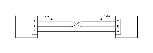
The RS-232-C standard supports full duplex communication using all 25 pins of the plug. You can get by with only 3 wires (send, receive and ground) if you ignore the control information. Frequently only 9 of the pins are used.
The transmit line of the terminal is connected to the receive line of the modem. In the RS232 standard, terminals are called Data Terminal Equipment and modems are Data Circuit-Terminating Equipment).

It is possible to design a system that sends more than just two values. Consider a system similar to RS232 that can set the transmission line to 4 different voltages, +15, +7.5, -7.5 and -15. Every time period one of these four values will be sent. Each value can represent two bits, such as +15 volts = 11, +7.5 volts = 10, -7.5 volts = 01 and -15 volts = 00. For every value sent, two bits of information are received. The rate at which values are sent is called the Baud rate. In this example the number of bits transmitted per second is twice the baud rate. One should be careful not to confuse buad with bits/second.
In 1924 H. Nyquist derived an equation relating bandwidth and maximum data rate
max data rate(bits/sec) = 2 * B * log2 V
where B = bandwidth and V = number of different values that can be sent. Hz = Hertz = cycles / second
This applies to perfect noiseless channels and gives the absolute maximum speed available. If you send binary values (V = 2) over a 3000Hz line, the maximum data rate is 6K bps. If you can send one of four different values (V=4), you can get a maxium data rate of 12K bps. The data rate would be 12K bps while the baud rate would be 6K.
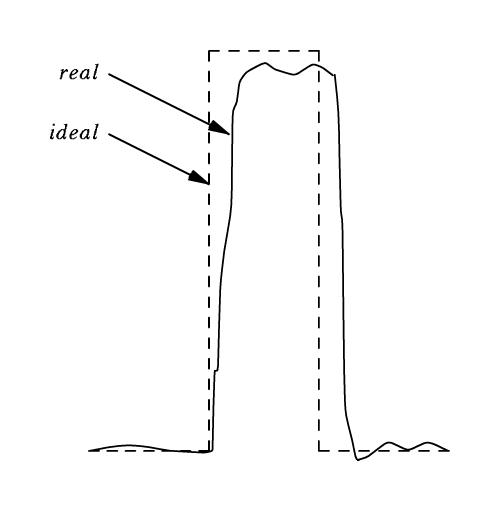
When a bit is transmitted over a wire in the real world, it is subject to noise and distortion.

Bandwidth is the range of frequencies that can be sent and received. All hardware has a limited range of frequencies over which it can operate. The human ear functions between 50Hz to 20KHz, so it has a bandwidth of about 19,950Hz. Filters in the telephone system allow only frequencies between 50Hz and 3050Hz for a bandwidth of 3KHz.
Real communication lines have noise, thermal noise. Noise is represented as a signal/noise ratio or the ratio of the strength (energy) of the noise to the strength (energy) of the noise.
In 1948 Shannon derived an equation for channels with random thermal noise:
max data rate(bits/sec) = B * log2 (S/N + 1)
Note that the "+1" is unimportant if we are talking about S/N
in the thousands. Noise is usually represented in decibels (dB). dB = 10 * log10
S/N or ![]() Substituting the expression for noise expressed in decibels
into the Shannon equation and simplifying to eliminate base 2 logs, we get:
Substituting the expression for noise expressed in decibels
into the Shannon equation and simplifying to eliminate base 2 logs, we get:
![]()
A good telephone connection has a S/N of 34 - 38 dB. This gives a max data rate of 33,885bps over a phone line.
Standards organizations